Hi all this is a part of one of our modules from our heat geek online heating design training course.
Please bear in mind, this is very much from the advanced section. All the trainees that would have gotten to this part, would have done all the maths necessary to understand exactly what's going on here. However, we’re just going to explain what's going on.
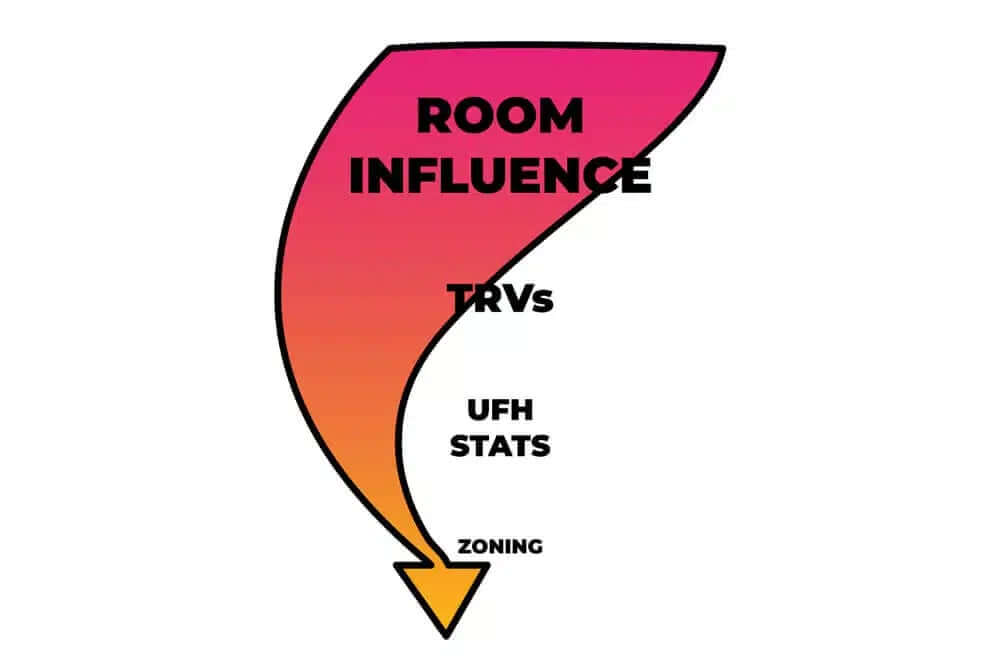
Room Sensor vs TRVs
Restricting the room temperature with a thermostat or TRV (thermostatic radiator valve) prematurely is like breaking and accelerating at the same time.
If using room compensation, the TRV or room thermostat closes down prematurely because it is out of sync with this room sensor, which can happen over time. The room influence controller will increase the target flow temperature at the heat source to compensate, and the two conflicting temperature controls will fight. This is why it is set up more like a temperature limiter rather than a control.
With pure open-loop weather compensation, it's more about keeping the flow rates up and allowing the self-regulation effect.
Thermostatic Radiator Valves
TRVs are slightly better than room stats, as these operate in a control band. These slowly close down as they reach the target temperature.
They don't just close down immediately and can sit in a semi-closed position to allow flow through.

Modulating Controls
This first section essentially says that we want to use modulating controls for our heat sources.
That control varies the flow temperature from the heat source, not just switching it on or off.
These dramatically increase the efficiency of heat pumps and a bit in boilers. For more information on smart stats, have a look at our smart stat video.
We wouldn't necessarily advise using TRVs or room stats to turn down unused rooms or spare rooms either. Turning unused rooms right down, or micro zoning, gives a particularly high risk of losing efficiency for heat pumps.
Creating too many zones in our system restricts the system volume and increases cycles, but most importantly, it increases the flow temperature required.
Flow Temperature
Okay, this is a KEY POINT to understand throughout the whole of this article:
The lower the flow temperature inside your heat source, heat pump, or gas boiler, the more efficient it is.
We want to target as low a temperature as possible, as we know by maximising the surface area of our emitters; we minimise our flow temperature.
Closing down radiators effectively reduces the surface area to emit heat. The remaining radiators that are still on will have to run much hotter to compensate for the colder rooms next door. Here's an example we can work out together.
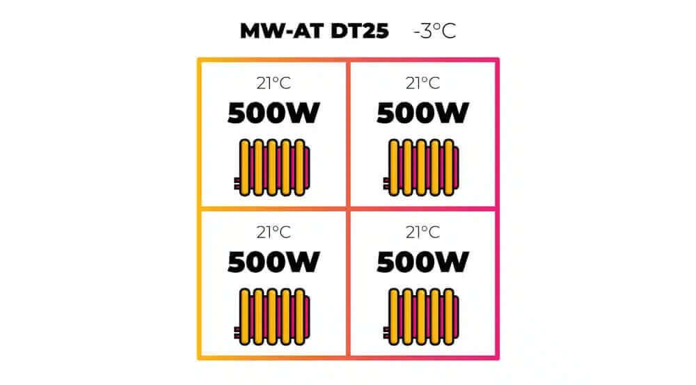
Let's take this four-room house. To keep the maths simple, each room has a 500 W heat loss at design outside temperature of -3 °C or 2 kW in total with a room temperature of 21°C. They are also each fitted with a mean water-to-air temperature ∆T 25 radiator, meaning that each radiator will output 500 W, when its average surface temperature is 25°C above the room temperature.
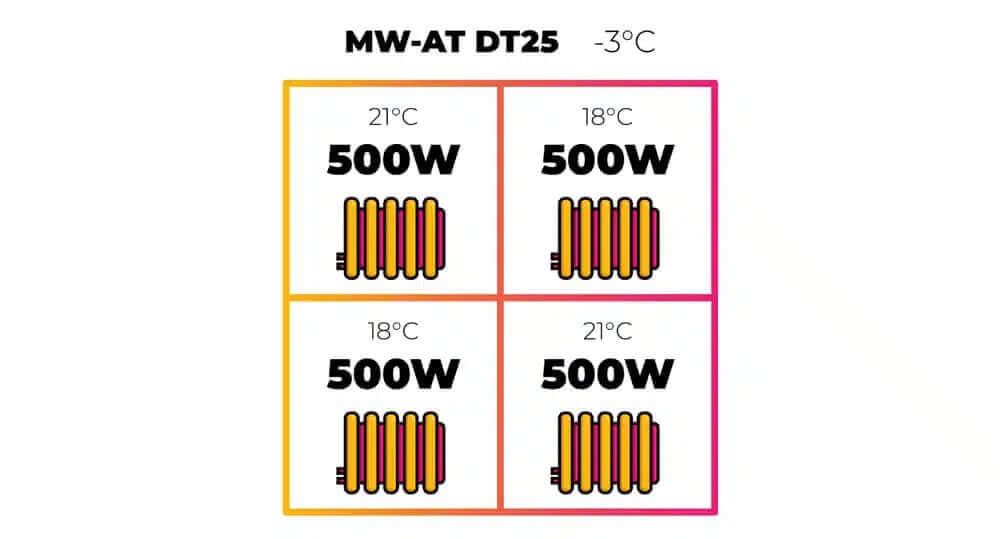
Now, let’s say you don't use two rooms, so you put them into a setback temperature of 18°C to save energy.
A quick way to see how much heat loss this saves is by working out how much power the property takes to heat by 1 K, at design temperature, multiplied by our new average property temperature.
- The property did have a heat loss of 2 kW, with a ∆T of 24 K:
500 x 4 = 2 kW heat loss at ∆T 24
This means it will require 83.3 watts per kelvin (2000 / 24 = 83.3 W/K)
- The new average temperature of the building is 19.5°C, which would make our new ∆T 22.5 K.
(21 + 21 + 18 + 18) ÷ 4 = 19.5°C(19.5 - (-3) = ∆T 22.5)
- Multiply these together and see that the new load would theoretically be 1874 W, if all rooms had similar heat loss.
22.5 x 83.3 = 1874 W
That's a 6.3% less energy loss
Heat Loss
This could be looking from above or a side view; it doesn't really matter. Turning down our radiators in the unused rooms to 18°C, in this specific scenario, has saved six percent heat loss from the property, which sounds great, or does it?
Remember, that's only if your other rooms do indeed drop to 18°C, whilst these other rooms are at 21°C. This is quite possible if you have solid, uninsulated external walls. But, for any building with a cavity or cavity insulation, even if your internal doors are permanently shut and with no one walking through them between rooms, they would still have to be very well-insulated and sealed internal doors, which is unlikely. Let alone having fully insulated walls between each of the rooms.
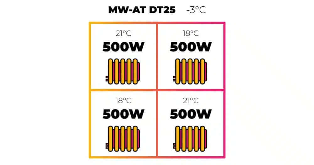
Let's say those rooms with a setback temperature of 18°C only drop to 19°C. Let’s work out the total heat loss from that building.
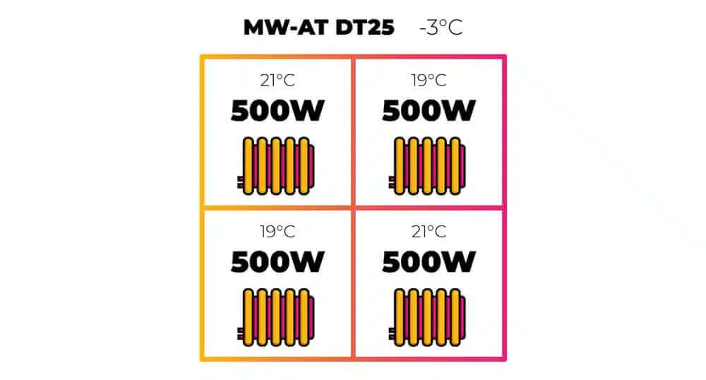
- If we add all our room temperatures together and divide by 4, this gives us a mean temperature of 20 degrees Celsius.
(21 + 21 + 19 + 19) ÷ 4 = 20°C(20 - (-3) = ∆T 23)
- If the building has a heat loss of 83.3 W/K, we multiply this by our ∆T of 23 to give a 1916 W heat loss.
23 x 83.3 = 1916 W
That's a 4.2% less energy loss
This means we've saved 4.2 percent of power or energy.
So here, we’re suggesting that because heat is lost into those cooler rooms, your heat loss isn't quite as low as you were trying to target when you were turning down those TRVs.
Yes, your radiators in those rooms aren't on, but the other remaining radiators are having to work much harder to get their rooms up to temperature and the result is that you could actually only be saving 4% .
Now remember, the property was fitted with ∆T 25 radiators, meaning they output 500 W when their average surface temperature is 25°C above the room temperature. What temperature do you think these same radiators would have to be, if the adjoining rooms were 18°C?
Let's say each internal wall is 2.3 m by 4 m, and each room has a 2 m2 door.
Internal Wall Area = 2.3 x 4 with a U value of 2 W/m2K
Internal Door Area = 2m2 with a U value of 8 W/m2K
- First of all, we would need to work out the heat loss into the other adjoining rooms. 2.3 x 8, to account for both walls in the room, gives 18.4 m2.
2.3 m x 8 m = 18.4 m2
- Take 2 m2 away for the door, which gives 16.4 m2.
18.4 m2 - 2 m2 (internal door) = 16.4 m2
- Multiplied by our U-value of 2 W/m2K is 32.8 W/K.
16.4 m2 x 2 W/m2K = 32.8 W/K
- Multiplied by 3 degrees temperature difference between the rooms gives 98.4 W heat loss, between the 21°C rooms and 18°C rooms, through the walls
32.8 W/K x 3 K = 98.4 W
- Take the 2 m2 internal door and multiply it by its U-value of 8 W/m2K. This gives 16 W.
2m2 door x 8 W/m2K = 16 W/K
- Multiplied by 3 degrees is 48 W.
16 W x 3 K = 48 W
- This totals 146.4 watts of additional heat loss from each 21°C room.
Total = 146.4 W heat loss (98.4 W + 48 W)
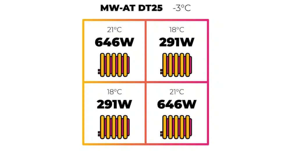
So the mean water-to-air temperature ∆T 25 radiator, which produces 500 W, will now have to produce 646.4 W. (500 W + 146.4 W)
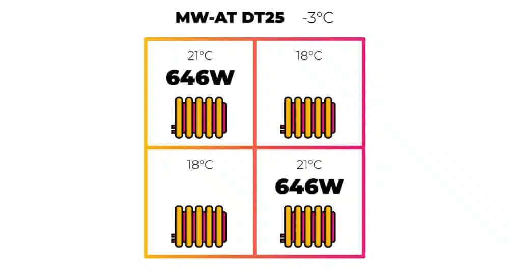
If you remember, the property required 1874 W. If these two radiators are inputting 1292 W, the remaining 582 W will be emitted into these two cooler rooms by their respective radiators, with either the TRVs restricting the flow right down. Or, it could just be a room stat that's set to 18, that's pulsing the heat on and off, into the room.
To calculate the temperature required to make a 500 W (MW-AT 25) radiator output 646 W, you can rearrange our radiator conversion factor using some of the previous principles you've learned (if you’ve done the course).
- First, let's determine how much more power it has to output. 646 W divided by 500 gives 1.292 that's 29.2 percent more power required from the radiator.
646 W ÷ 500 W = 1.292
This is 29.2% more power required
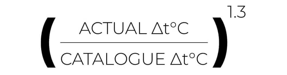
We now have to account for the non-linear relationship between MW-AT and the heat output of radiators, which you might remember features an exponent of 1.3,. However, we're working the other way around here. So rather than going from ∆T difference to the power increase, we're going from the power increase to the ∆T. So we'll have to use the reciprocal of 1.3.
- Remember to find the reciprocal, we divide the number 1 by the number we want to find the reciprocal of: 1 divided by 1.3 is 0.77.
1 ÷ 1.3 = 0.77
- We take our 1.292 power increase to the power of 0.77, which gives 1.22 rounded up.
1.292^0.77 = 1.22
- Your radiator’s mean water-to-air temperature will have to be 1.22. That's 22% hotter to output 614 W. So if the mean water-to-air temperature ∆T was previously 25°C, the new mean water-to-air temperature will have to be 30.5°C.
25 K x 1.22 = 30.5°C
- Now, with a 21°C room temperature, our mean water temperature would have been 46°C at the design outside temperature. However, it will now need 51.5 degrees celsius.
Old mean water temperature = 46°C (21°C room temp + ∆T 25)
New mean water temperature = 51.5°C (21°C room temp + ∆T 30.5)
Heat Pump Efficiency
Essentially, the point here is that by turning down or off zones, the remaining on zones will have to run much hotter and with a heat pump, which directly means higher fuel bills.
Take a look at this cop graph for a Mitsubishi Ecodan heat pump. Remember, this lower line is for 2 degrees outside temperature, but let's use it as an example.
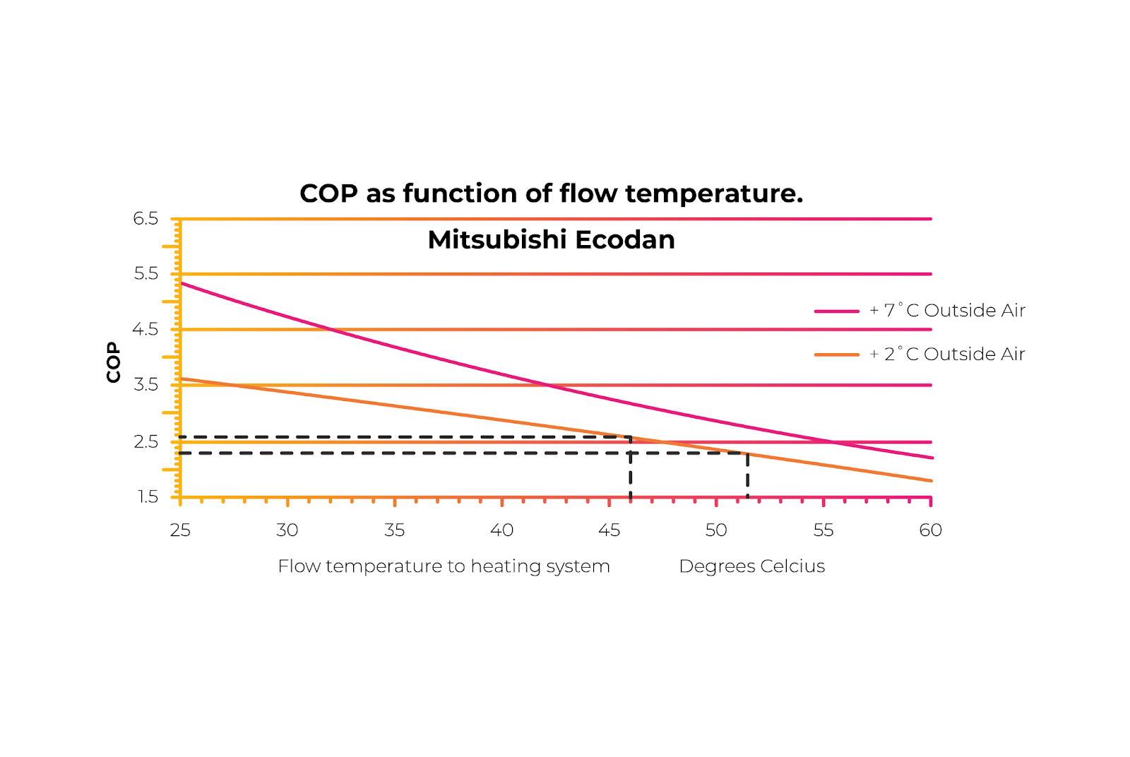
If you run the house with all the zones open and at the same temperature of 21°C, you would need a flow temperature of around 46°C (will be high depending on heat pump ∆T), giving you a COP of 2.6.
This will consume 769 W of electricity to produce 2 kW of power from the heat pump. That's 2 kW divided by our cop of 2.6.
2000 W ÷ 2.6 = 769 W
If you zoned down the property to a heat loss of 1874 W, but ran at the new required flow temperature of 51.5 (will be high depending on heat pump ∆T), the COP would reduce to 2.3.
Using the same COP calculation, we can see that you would require 815 W of power in this scenario. That's 6% more power required, despite the property requiring 6.3% less heat.
1874 W ÷ 2.3 = 815 W
This all fits relatively well with the rule of thumb that for every K hotter the heat pump has to run, you lose 2.5% efficiency.
This illustrates the point clearly that zoning isn't necessarily a good idea. The efficiency curve for gas heating isn't quite so steep, but there is still an efficiency curve nonetheless, so it should be considered when choosing a setback temperature and how much to zone.

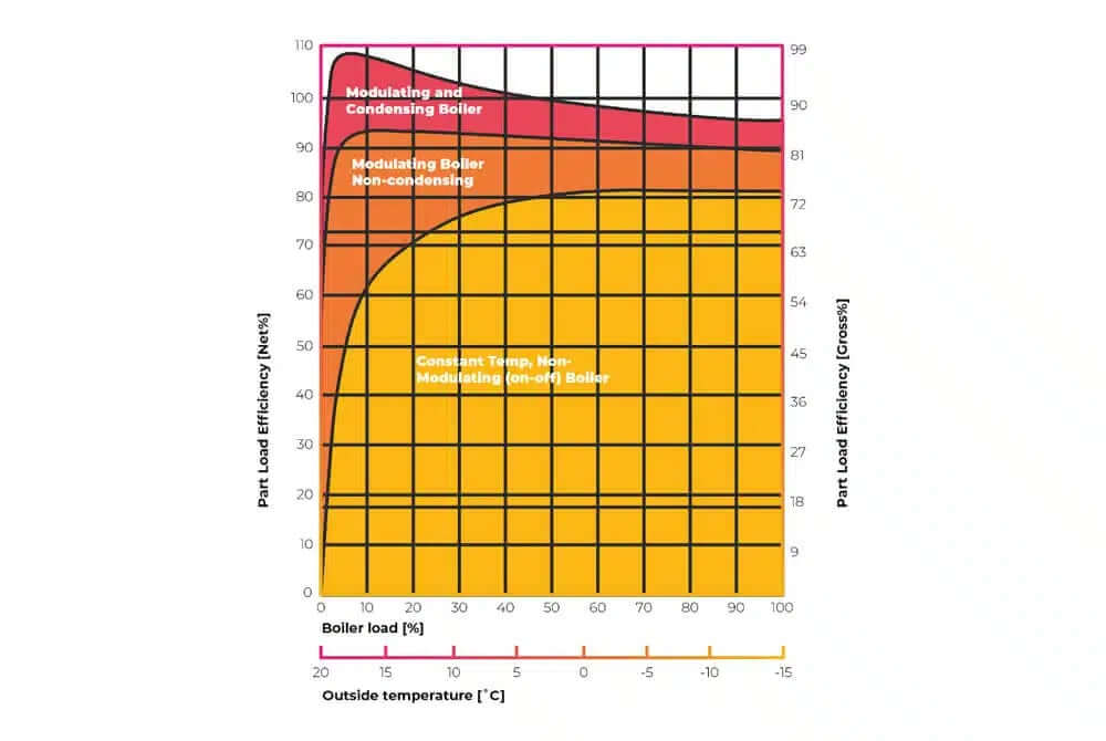
Gas Boiler Efficiency
Take a similar situation but using a gas boiler. If you reference the above graph, you'll see that you could save approximately 4% efficiency with these flow temperatures or even up to 12% efficiency with different flow temperatures.
Where the complication comes in with gas boilers is the below graph, which shows part load efficiency. This is where the lower the output of the gas boiler, the higher the efficiency. We won't go into that today, though.
Let's take this one step further with another example and assume that the two off rooms in our scenario were turned completely off to the frost setting at the TRV, by our customer. However, assume the two off rooms settled at 18°C. This would mean the internal and external walls would have a slightly different insulative value. What mean water to air temperature would these radiators require, remembering that our property heat loss will be 1874.
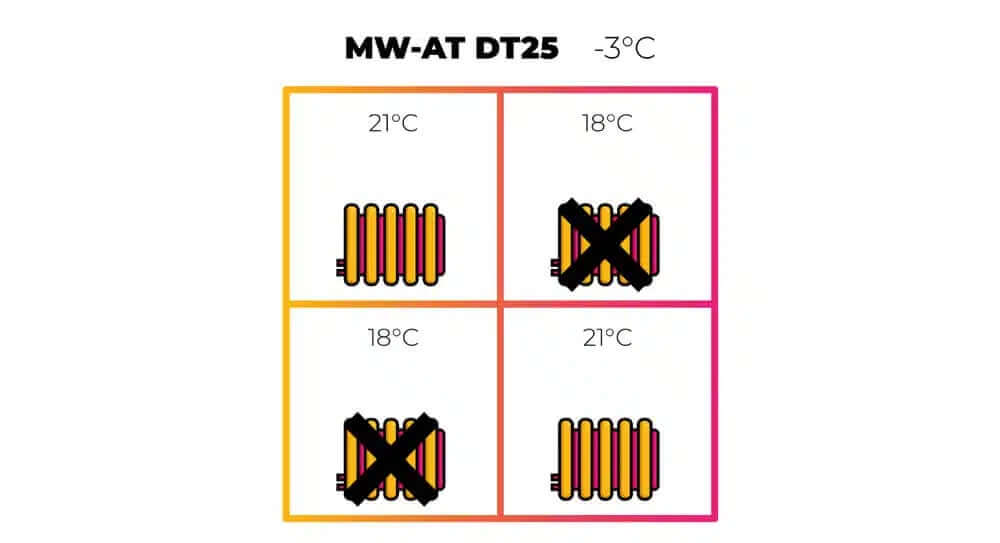
- Now this one's a little bit easier to work out the heat requirement from each radiator. We would divide the heat loss by two. Each radiator is required to emit 937 W.
1874 W ÷ 2 = 937 W
- 937 W required now divided by the 500 gives a conversion factor of 1.87.
937 W ÷ 500 = 1.87
- 1.87 to the power of 0.77, which is the reciprocal of the exponent for radiators, is 1.62. Our mean water-to-air temperature will have to be 62% higher to increase from 500 W output to 937 W output.
1.87^0.77 = 1.62
- Our previous ∆T 25 radiators will now need to run at ∆T 40.5.
∆T 25 x 1.62 = ∆T 40.5
- If the room temperature is 21°C, the temperature from the heat pump will now need to be around 64°C. This isn't possible for the vast majority of standard heat pumps.
64°C Flow temperature required (61.5°C Mean)
Heat Pumps Efficiency
So in this example, where the customer's completely turned off some zones or radiators, the heat pump COP has gone from 2.6 right the way down to 1.6 and used 52% more power than if they just left all the radiators on, despite the property losing 6% less heat.
In real-world terms for the customer, if they were paying say 15 pence per kWh, this 2 kW house, in full load conditions and with all the rooms turned up to 21°C, would cost 11.5p per hour to run. However, once turning down two rooms to 18°C, the new price per hour to run is 18p, despite two rooms being 3 degrees cooler.
And not only will this have a disastrous effect on COP and fuel bills, the 21°C rooms won't ever be able to reach temperature.
Now this isn't to say you should never zone. There's lots of variables here like building shape, layout, system mass as well as other sources of heat to consider.
However, we've been favourable to zoning with these calculations, as particularly with heat pumps, zoning increases one other rather large inefficiency that's not accounted for and that inefficiency is increased cycling.
Due to built-in anti-cycling, gas boilers only have minimum losses from cycling, however, heat pumps have considerable losses on startup, as you can see here.
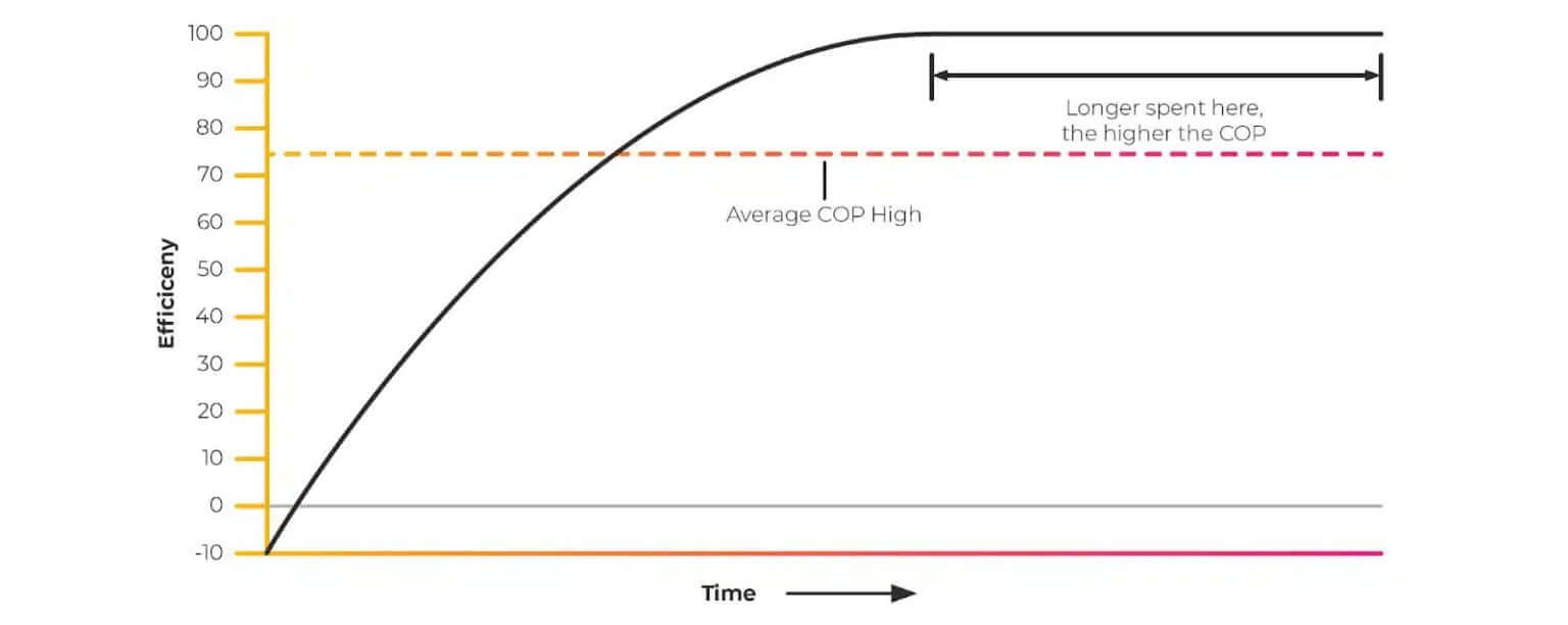
Heat pumps don't reach maximum efficiency for a while after they've started. The compressor needs to increase the pressure enough to evaporate the refrigerant and begin the cycle.
The compressor is turned on and initially has a negative efficiency. It then slowly climbs to its maximum efficiency over time and the longer it's left at maximum efficiency, the higher the COP is dragged up.
If the unit then turns off, this cycle has to start over and the result is that the average efficiency is dragged right back down.
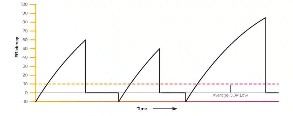
One more variable to add to this, is that the compressor is most efficient at maximum output. When the compressor speed slows, it actually drops in efficiency.
There are two ways we can ensure this sits at the maximum output as much as possible.
- We ensure we have as much volume as possible
- We ensure the run times are as long as possible
Advanced controls often have adjustable minimum run times or cycle rates built in, but you can't adjust these with no ill effects. The wider you set your cycle rates, or time between ons and offs, the wider your temperature swings in room temperature.
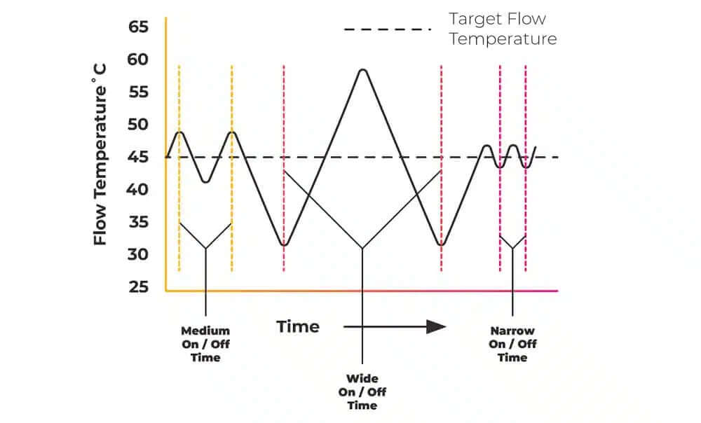
Conversely, the narrower you have your time bands, the more accurate the room temperature with under an overshoot, yet, the less efficient the appliance.
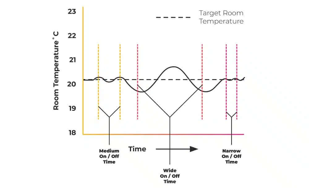
Additionally to that, the lower your volume, which can be caused by zoning down, the wider you're over an undershoot.
Advanced Controls
So increasing the flow temperature is one factor, but turning off radiators or underfloor heating zones also increases this cycling, which is the switching on and off of the appliance. This decreasing efficiency is on top of our previously calculated figure.
The advanced controls built into high-quality heat pumps and high-end boilers are something you'll have to play with and get used to. They are specific to each manufacturer. They have a lot of adjustable parameters built in to suit specific heat source preferences.
Using a third-party control to send an on or off signal to these heat sources and bypassing its natural functionality potentially damages COP and running costs.
If you do, you'll have to set a higher than-necessary weather compensation curve to account for the fact the heating is more intermittent and the energy being lost from the building is not matched by the energy going in, on a continual basis.
This is why you may hear engineers say you want to leave your heat pump on all the time, but by this, they shouldn't necessarily mean at full target comfort temperature. You can still have an off temperature or what's known as a setback temperature.
This again isn't something that's the same for every scenario, property and heat source but in the case of a heat pump, you want to have a relatively high setback temperature.
With advanced weather compensation, rather than turning the heat source off at night, the system just drops to a setback temperature.
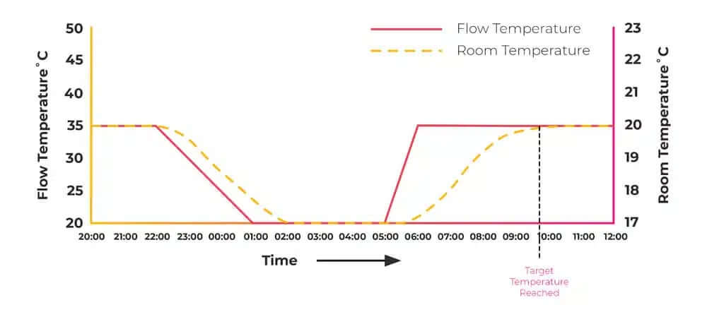
Let's say it's 9°C outside. Our target room temperature is 20°C and our heat pump's flow temperature is 35°C.
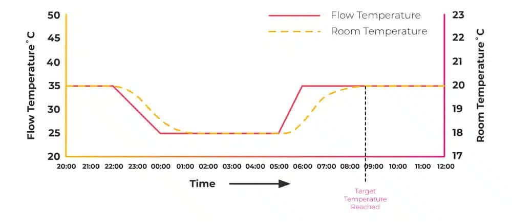
If we have pure weather compensation, the flow temperature will drop to what would be required for our setback of say 18°C, which might be a flow temperature of, say, 28°C.
Because the system will be warm, the unit will turn off for a while whilst the system cools. It will then re-fire to maintain a flow temperature of 28°C.
If your curve is set accurately, your property will cool to 18°C, but no more. This keeps your walls, pipework system and thermal mass fed with thermal energy.
If you turned your system completely off, the internal temperature could drop to below 18°C, and the heat source would have to fire far hotter to replace that energy, which had also been lost in the system, especially if you have underfloor heating. Otherwise, the room temperature will take a long time to come up to its set temperature.
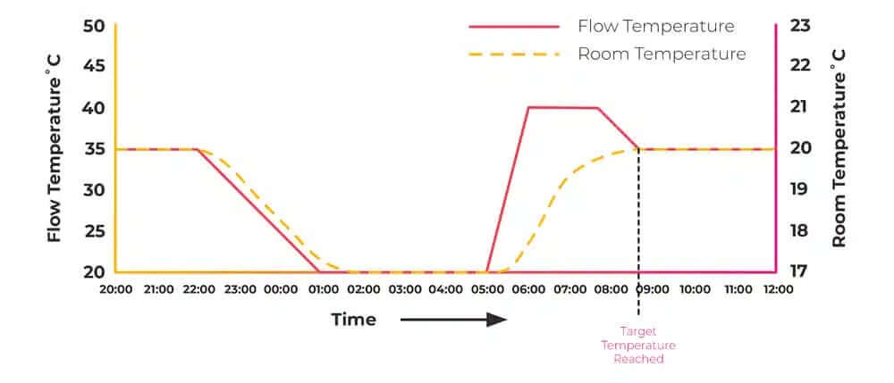
Once the heating schedule returns to 20°C , the heat source will again be able to keep cooler, as the mass of the property and system has been fed.
Any kind of room influence or closed loop control will work against this. Again, it's not a hard and fast rule, as there are many variables.
So if you're a fan of rules of thumb, this is why it's advised that the setback temperature for gas boilers should be no more than 3 degrees below your comfort temperature and two degrees for heat pumps, so the property mass is fed, the flow temperature is kept as low as possible. Again, this depends on lots of other variables, particularly thermal mass.
The Recap
So just to recap, heat pumps, in particular, need a high volume to run effectively and efficiently, unless you have better internal insulation than external insulation.
Installing zone controls may have the opposite effect of the one they're advertised or intended to have. You can reduce cycling by installing things like buffers, but that has an installation cost, a space cost and has an efficiency loss in itself. Look at our video on low loss headers to find out how.
Beware, there are some situations where you would or should, so it's really a case-by-case basis. This is really to highlight this other big variable that we have, when deciding to zone. This is why we’re not too much of a big fan of regulation or British standards. Every situation is different and needs a different engineered approach.
If you're an end-user and could do with the help of a trained heat geek, check out our interactive map where you can find engineers that have undergone our full training and remember our course, unlike others, isn't a pay-to-pass so any engineer on our map is fully tried and tested.
If you're an engineer and want to find out more about our training, head over to heatgeek.com and don't be worried about all the maths. We build you up to what you've seen here and we have a full-time, 24/7 support group to help you through with like-minded engineers.