What is a Low Loss Header?
A large tube of empty pipe. end.
No seriously, low loss headers aren't complicated or some mysterious art. It's just a large tube or box of water with the flow and return connections to allow a flow of water and heat.
What Does a Low Loss Header Do? And Do You Need a Low Loss Header?
First, if you want to see how much it could cost to have a heat pump installed in your home then use our instant estimate tool below.
Low loss headers are typically used as 'hydraulic separation' between any two or more circulating pumps within a heating system. This hydraulic separation allows each pump to work independently at its own flow rates. Without pulling or pushing on the other.
Without some form of hydraulic separation installed, the connected pumps will not be able to run at their own specific flow rate for that zone. This can cause issues like reverse circulation and also unbalanced systems.
An additional problem with two pumps pulling or pushing on one another, particularly with modulating pumps, is that they will interfere with each others feedback response. This can cause an erratic and oscillating/pulsing reaction between one another.
Two non-modulating, fixed output pumps will be less of an issue.
Why Would You Want Two or More Pumps on a Heating System?
Typically you will see low loss headers in commercial installations where there could be many pumps. Each is sized for their individual task or zone. In domestic or smaller commercial heating systems, however, they are typically installed where the internal boiler pump doesn't have enough power or speed for the system.
For example, underfloor heating requires a flow rate 3 times that of radiators to ensure an even floor temperature. Boiler pumps can struggle to achieve that higher volume. Or, if you have a well-insulated large building, or a building with particularly small pipework, the resistance of all the pipework and bends may be too much for an internal boiler pump to overcome with adequate flow.
In both these situations, you would install low loss headers.
How Does a Low Loss Header Work?
As we all know, water will always take the path of least resistance. The large chamber inside a low loss header creates a shortcut across the flow and return pipework. If a boiler with an internal pump, pumps to a low loss header, almost 100% of the water will return back to the boiler.
Very little flow, if any, will continue on to the system. This allows a system pump to be installed on the other side of the header and operate in much the same way with minimal disruption to the boiler side of the Header.
Low loss header's aren't just for multiple pumps though. They can be used to connect multiple boilers and heat sources to a single system. There can be many hydraulic problems with multiple heat sources that an LLH or buffer (an extra-large LLH) gets around.
There are even slightly more complex low loss headers that allow for the different flow and return temperatures of varying heat sources. These use baffle plates to divert the lowest returns to the best heat sources to maximise efficiency and effectiveness. Some buffers have multiple tappings and jackets that utilise the stratification of the store (warmer water at the top and cooler at the bottom) to create a kind of heat battery which again allows systems to utilise heat sources with different flow temperatures.
Other Benefits to Low Loss Headers
When the flow of water reaches the large bore of a header, the water immediately slows right down to at least half the speed/velocity it was travelling through the pipework. This environment allows suspended dirt particles to drop to the bottom of the unit, and small air bubbles will also separate out and rise to the top. The bigger the unit, and in turn the slower the flow through the unit, the more effective the LLH will be at this dirt and air separation. A further advantage here is that, unlike magnetic filters, this low-velocity filter will also collect non-magnetic dirt such as copper, brass, tin, and lead. Even steel and iron from traditional system corrosion lose their magnetism over time.
It's worth noting this advantage is only available if the header is a vertical type as opposed to horizontal. The designers have also given flush and venting points. Some manufacturer takes this one step further by installing a mesh-type turbulator. This will help the separation of dirt and air, although we would advise caution were using some of these.
Are There Any Downsides of Using a Low Loss Header?
Provided that it's well insulated, as it has the potential to be a rather large unwanted radiator, the main downside is the additional cost. However, if you require multiple pumps or heat sources, this can't really be avoided in a very elegant way.
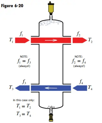
The one issue that you can get from using any hydraulic separation, however, is distortion. See the vid above from back in 2017. Essentially distortion refers to the higher temperatures required at the boiler in order to get the emitters (typically rads or underfloor heating) up to a suitable temperature if the flow rates on either side of the low loss header differ, which they nearly always will. These higher temperatures in the heat source can cause a small % loss in efficiency with gas boilers. Even more so with heat pumps, as well as all the other associated issues with higher temperature systems noted here. It is caused by mixing or blending the flow and return water within the header. It does not refer to a warming of the boiler return, but instead the equally higher flow and return temperatures required at the heat source compared to the emitter.
This is not reason enough to not fit a low loss header at all. But more of a reason to more carefully consider if it's genuinely needed or if it can be designed out. If one is required, distortions are something to minimise on commissioning of the system if you want to maximise efficiency and system performance. If not commissioned by a competent engineer can possibly lead to insufficient emitter temps, room temperatures and slow cylinder loading times.
How Can I Avoid Using a Low Loss Header?
https://www.youtube.com/watch?v=mNcRx45DQ8M
There are many reasons you may want to avoid installing a low loss header. For example, cost, space or system simplicity. To avoid using one would very much depend on the reason you require one.
Firstly, get your calculations right. There's a pandemic in this industry for hugely overestimating heat requirements for properties. An overestimated heat load will result in unrealistic flow rates and results in exponentially higher calculated system loss.
Rules of thumb become quickly outdated. Especially when oversized systems still 'work', unless you have a dynamic system that accounts for insulation, I wouldn't bother. We have a guide to property heat loss which may help here with quick guides to check your rules of thumb against. To learn how to calculate your flow rate requirement, see this article on mass flow rate.
Once you are sure your calculations are correct, the requirements for a low loss header usually comes down to 3 main reasons.
High flow rate requirement in the system, high resistance across the system/boiler pump is too small, or multiple heat sources for the property.
High System Resistance or Boiler Pump is Too Small
There are a few ways to avoid installing a low loss header if you are simply installing one because you don't believe your boiler pump to be up to the job.
Firstly, it is worth noting that since the ERP directive came in to make all pumps modulating. Nearly every single internal boiler pump is now a 7-meter heat pump. 20% higher grunt than the previous 5/6m head internal pumps. You may be surprised where the newer limits are.
Secondly, Install a bigger pump. If you are working on a system where the pump is external to the boiler then upgrading the pump will give more energy where it's needed at a fraction of the cost and complication. Assuming you know your old pump wasn't faulty or weak, in which case your pump just needs replacing.
Lastly, upsize where possible. If your calculations are close, it may be more practical to upgrade some components. Especially if you are already doing work such as replacing the boiler. Upgrade the primary pipework bore, upgrade thermostatic radiator valves to full/larger bore and lockshield valves to full bore or lower KV value valves on the furthest radiators. Often simply upsizing the main boiler/heat source to the nearest main tee is more than ample, as the flow rate and pipe resistance will dramatically drop after this point.
System Flow Rate Requirement is Too High
If your main reason to avoid a low loss header is space then a close-coupled tee (or closely spaced tee, if you prefer) is your friend here. A closely spaced tee is a pipework orientation including 2 tees that are closely spaced, funnily enough. The close proximity of the tees means the pressure loss between them is so low that you can create two separate hydraulic circuits that will work independently and inflict minimal flow on one another. This is the same principle as a low loss header and where a low loss Header gets its name. More on close-coupled tees.
If you have both radiators and underfloor heating, the high flow rate required at underfloor heating often outstrips what the boiler can cope with, in this instance, we suggest a close-coupled tee at the underfloor heating manifold along with a zone valve and a balancing valve to avoid leaving a system bypass. The boiler pump can then serve the radiators as required.
Again, I would check your calculations. Way more often than not, old rules of thumb no longer work. It is possible to run a new-build 3-bed house entirely fitted with underfloor heating just off the boiler pump in some circumstances. Let alone a flat. In reality, every property is vastly different.
If your pump is external to the boiler or heat source, we would advise checking the boiler's maximum permissible flow rate to see if you can simply upgrade the external pump for a larger one. Some engineers wish to take this data with a pinch of salt though. This is because you will find that the maximum permissible flow rate seems to be relative to the boiler output.
Despite most boilers having exactly the same internals throughout their range. We are sceptical about boilers maximum permissible flow rates but would always advise following manufacturers' instructions of course.
Multiple Heat Sources
There is no way of avoiding this in a technically correct way. Low loss headers are the perfect tool here anyway and should be embraced.
If you are using multiple AND different types of heat sources, better still would be to use a buffer. This has a much better way of controlling and utilising different flow temperatures from the sources and maximising efficiency. Although, it adds cost and can take up valuable space.
Low Loss Header Design
There are 4 basic rules we would suggest the following when it comes to low loss header design and this is fine for large domestic/small commercial applications. However, you will still see these rules used for larger installations too.
Sizing, 1 Keep Velocity Below 0.3m
The main aim of a 'low loss' header is to minimise pressure loss between the ports. This is what minimises the influence of the pumps on each other. Although the low-pressure loss is where a low loss header gets its name, to save long-winded and unnecessary calculations, a basic rule of thumb is to keep the velocity of the water below 0.3mps. This means that the easiest path for the water to follow will be right back to where it came from.
To work this out, you will have to work out the maximum flow rate of your system. Then, convert this to velocity for your chosen header diameter of header. You will also read figures such as 0.2mps velocity for low loss headers but for basic domestic systems and small commercial. We find 0.3 fine as a maximum just fine. Larger bores will give lower velocity and aid in air and dirt separation; however as always, there is a balance between cost, size, and returns. To work out the flow rate and velocity, follow our guide to mass flow rate.
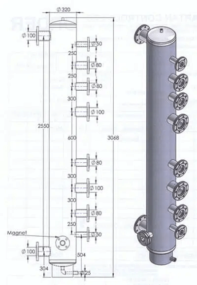
Do Not Use Multiple Tappings
Out in the field, you will regularly see multiple tappings on headers, which in our opinion, is a big mistake. Multiple tappings are where rather than having 1 single flow and return for your heat source side of the header and one flow and return for your system side (aka primary and secondary side), you have different tappings for different circuits or heat sources. This was/is used because you can pump straight off of the header with no need to install zone valves or other fittings such as check valves to stop reverse circulation when one zone is turned off.
Multi tapping low loss header
The problem with multiple tappings is that when more than 1 circuit is turned on, you end up with some circuits short-circuiting and using return temperature water as flow water. Resulting in some circuits being hotter than others.
If you have multiple circuits, we would advise installing them to 1 single common pipe. Different pumps can be taken off. This however will potentially interfere with each other and potentially cause reverse circulation or influence other pumps' flow rates. You can and should fit zone valves and/or non-return valves to prevent reverse circulation in this situation. Or, instead, use a distribution header.
Use a Distribution Header Where Possible
A more simple way of connecting multiple circuits to a low loss header, without the need for zone valves or non-return valves that could potentially fail, is to install a distribution header. This is simply where the common pipe connecting the different circuits is sized, again, for a low velocity (sub 0.5mps). This gives the exact same low-pressure loss effect as the low loss header. And means your individual pumps will perform the same in all system scenarios and not allow reverse circulation.
Your distribution header could be the same size as your Low loss header, which essentially just makes the whole fitting one large, sideways, 'H' shape header. But will maximise performance and minimise moving parts. The downside, of course, is space and expense. Which could very well be hard to justify on small commercial, let alone domestic installations.
Thou Shalt Avoid Horizontal Headers
Horizontal Low loss headers are just as they sound. A low loss header turned on its side. They are great for saving room and often come with commercial boiler installation packs. However, it lacks the ability to separate air and dirt as efficiently. Without this added benefit, we see little benefit over a close-coupled tee installation in domestic installations. Perhaps if you are installing multiple boilers and the room is tight. As always, though, there is no one size fits all and engineering judgment has to be used.
Further Reading
Riello guide to low loss headers - This guide refers more to the pressure loss aspect of low loss headers. This is really the crux of what low loss headers and hydraulic separation are all about. The above explanation doesn't go into this too much for simplification. They mention 'recycling' (others call this mixing) on pages 9,10 and 11 which leads to distortion. But again, no mention of the negative impacts on condensing boilers.
Idronics #15- This is a great place to learn about hydraulic separation. Although beware, we find their information a little outdated. Especially when they refer to hydraulic separation in series regularly. Yet have no mention of the negative impacts or loss of efficiency with condensing boilers. It seems most of their information (as much American information) refers to non-condensing technology. They do mention mixing in the header but again no mention of the downfalls which again we find dated.
Don't forget to sign up for our newsletter for our latest articles!